Search

XTRX – A Fairwaves tiny SDR

High performance Software Defined Radio in a tiny miniPCIe format. Embedded applications, massive MIMO, IoT, 4G/5G and space ships.

07 – XTRX pinout

First of all – the project is not dead. 🙂 We decided to spend a bit more time optimizing RF performance to make sure we don’t disappoint you.

Meantime, some people are already adding support for XTRX into their future products, so we’ve prepared an XTRX pinout to facilitate this development.

Add XTRX support into your next product as well!

UPD May 4, 2017: Uploaded rev7 of the pinout datasheet with minor corrections.

XTRX rev3 pinout (click to download pdf)

06 – MIMO and independent receive/transmit

We often get asked how many receive and transmit chains does XTRX have and whether you can tune them to different frequencies, so I decided to clarify this once and for all.

XTRX is a 2×2 MIMO transceiver, which means that Continue reading “06 – MIMO and independent receive/transmit”

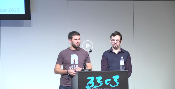
05 – Update & 33с3 Talk: Lessons learnt in building a low latency, high throughput PCIe based SDR

Talk

We recently gave a talk and a workshop at 33rd Chaos Communication Congress aka 33C3 on funny and not so funny issues one faces while building a high performance SDR. If you missed 33C33, video recordng of the presentation is available here (and slides are attached here).

When we prepared the talk, we listed all challenges Sergey had while debugging PCIe, but the list went so long that we had to move it to a separate workshop. So this talk was focused on more generic issues without going deep into PCIe internals, which I hope will be interesting for a wider audience working on SDR devices and aiming to achieve maximum performance.

Update

We know the blog has been silent for a while, but the talk shows some of the challenges we have been facing in getting the most out of XTRX. And the significant effort that is being put into making a solid product which “just works” – as far as it’s possible with SDR of course 🙂 .

At this moment we’re very close to place an order for the next prototyping run which (if no new critical bugs shows up) will be available for selected early adopters.

Stay tuned!

cc3c-talk-image


04 – First prototypes

XTRX in hands

Just got the first batch of test boards. Feels really good to hold them. Onto the testing.

03 – First Batch of PCBs!

IMG_20160628_145011

First prototype PCBs are ready for assembly at our fab! Can’t wait to get our hands on the prototypes.

Meantime Andrey Sviyazov has found the first hardware bug, so we know where will have a wire on the prototypes! (every device prototype should have a wire or it’s no fun) We have an RF switch to switch bands and we connected it to 1.8V control lines. But according to its documentation:

VHIGH = 2.5 V to VDD
VLOW = 0 to 0.8 V
Any state other than described in this Table places the switch into an undefined state.


PS SMT (Surface-mount technology) is a technology used to populate bare PCBs with SMD (surface-mount device) components – basically, a robot putting components on a board and soldering in an oven. XTRX don’t have any through-hole components, – all components are SMD – which means it will be assembled by a robot without any manual soldering. An important optimization for mass production.

PPS – You don’t need a robot if you are resourceful – see http://lowpowerlab.com/blog/2013/03/10/moteino-manual-pick-and-place-smd-assembly/


02 – SPI is now working

So while we’re waiting for the first test run of the boards to be manufactured, I have been working on advancing the software side of things.

Check out the below video where Alexander walks through the development rig and demonstrates a “Hello World” app – using SPI to control the LMS7002M chip and generate a sine wave. While sounds easy, it actually requires the whole stack to work in coordination as control commands travel through Linux userspace => Linux kernel module => PCIe => FPGA => SPI => LMS7002M.

Next steps are now to get I/Q data transfer up using DMA transfer over PCIe. Stay tuned.

UPD: See pages 14-16 of the LMS7002M data sheet for the details of the LMS7 SPI interface.


01 – Tech specs for the XTRX

A number of you requested more technical information on the board. Below are the most important parameters of XTRX. We will provide a more detailed view into each of these in followup posts.

  • 2×2 MIMO Lime Microsystems LMS7002M FPRF frontend with 100kHz – 3.8Ghz tuning range
  • miniPCIe form factor (30×51 mm).
  • <10 us bus latency, stable over time.
  • up to 160MSps@12bit per MIMO channel or (theoretically) even 240MSps@8 bit per MIMO channel in 2×2 MIMO mode (8Gbit/s total bus bandwidth).
  • GPS-disciplined clock with initial 280 ppb stability, <10 ppb after GPS lock.
  • Programmable sampling rate (30.72 MHz reference clock)
  • Software controlled switch for Rx/Tx antennas band selection. No more RF cable switching.
  • Multiple XTRX boards can be synchronized with each other to form a massive MIMO system.
  • Low bus latency allows offloading parts of DSP processing to the XTRX onboard FPGA.

Why PCIe?..and not USB3 like in most inexpensive SDRs? Like with the UmTRX line, we were aiming for something that is easy to start playing/prototyping that easily translates to a commercial design. From our experience, a lot of production systems feature a PCIe or miniPCIe bus which is robust, low latency and high bandwidth – a perfect choice for a high performance embedded SDR (Look at the bus specs above, you can only get that with PCIe) plus we don’t think USB is a solid mechanical connector for a field device requiring months of unattended operation.

If you don’t have a miniPCIe or PCIe slot,  depending on interest we’re planning an accessory to make it easy for everyone to use this board everywhere.

Price?  Expect the same ballpark as a BladeRF SDR. As mentioned in the first post, our aim is to increase accessibility. Embedded devices usually cost premium for their robustness and durability and are out of reach for most users. With XTRX we’re aiming at bringing this industrial quality to masses.

00 – First Post! It’s Tiny!

Now that Umtrx 2.3.1 is out , we wanted to give you a sneak peak at the next SDR board we’ve been working on. We’re calling it XTRX.

Andrey Sviyazov just finished the design and here is a render against a credit card to give you an idea of size.

Credit-card-and-Xtrx-2-white-bgrd-mini
Yes it’s really that small! The XTRX is a high performance/high bandwidth software defined radio (SDR) board that is specifically designed to support innovations around high data rate applications like 4G/5G and massive MIMO.

We also think the networks of the future will be more agile, flexible, programmable and distributed. This needs a foundation in great hardware. XTRX is our attempt to solve for that and make such hardware accessible.

Watch this blog/twitter for more updates as we make this real. Feel free to send feedback, early comments/interests  to xtrx@fairwaves.co

Blog at WordPress.com.

Up ↑